Book Cover Design
Designing book covers in Affinity Design 2 and cutting with Silhouette Cameo.

Overview
I’ve made around a half dozen covers in Affinity, and it feels like every time I walk away for more than a month all my hard-won knowledge evaporates, and I’m back to making rookie mistakes. How does the pen tool work again?
In this post, I’ve tried to consolidate a rough overview of my process, with some tips and tricks along the way…to hopefully finally break me out of the relearning cycle.
If you want to see finished covers made with this process, check out my Bookbinding Projects Log.
If you are completely new to Affinity and Silhouette, it’s probably a good idea to at least watch a couple tutorials online. I personally really enjoyed working through the videos by Design Made Simple.
Table of Contents
- Overview
- Design Process
- Setting Up Affinity
- Creating the Book Template
- Drawing
- Export and Silhouette Cameo Preparation
- Troubleshooting Common Issues
Design Process
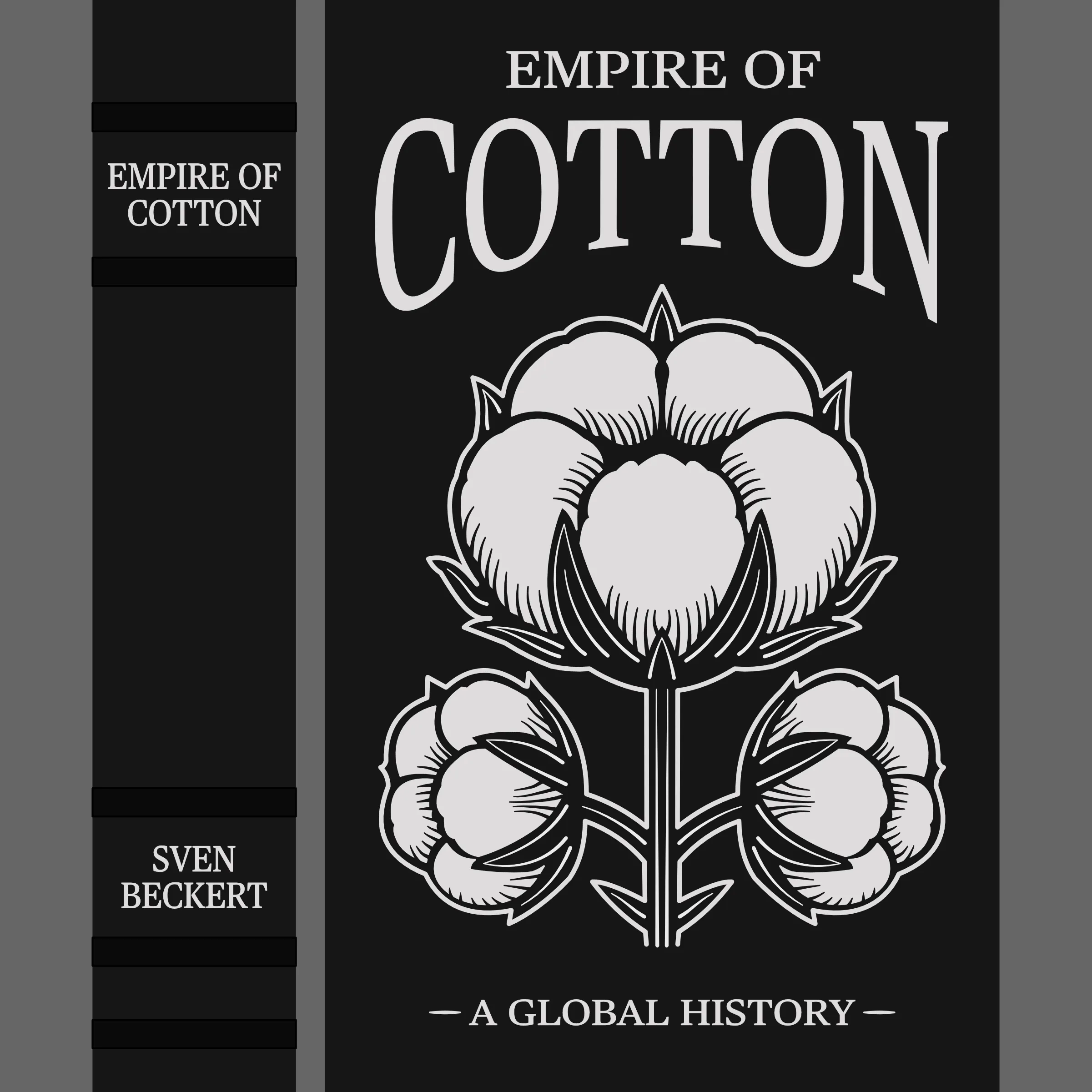
Although I’m sure some people can just hop into Affinity and smash out a cover from scratch, I’m just a lowly engineer and often need a bit of inspiration. Sometimes I like to simply modify the original cover into something more vector friendly, like with Making of the Fittest. Sometimes I really will draw almost completly from scratch, like with Demon Haunted World. However, I especially like using AI image generation as a springboard to flesh out ideas - or even make basic assets I can trace into vectors, like with Empire of Cotton.
If I had to outline my process, it would look something like this:
- Brainstorm initial concepts
- Use AI tools like ChatGPT for design ideation
- Import reference materials and inspiration into Affinity
- Create the cover
If you’ve never used a high-quality llm like OpenAi to get the creative juices flowing, I highly recommend it. You can prompt something like: “draw me a line art of a book cover for empire of cotton.” …which might be too complicated to cut with a silouette, so you can follow up with, “another one, simpler this time, with bold designs and clean lines.”


This back and forth is excellent for helping me narrow down on the vibe that I want, and I can sometimes even get components I like enough to directly trace into vectors. You can see how helpful the two chatgpt covers were in pointing me towards my final design.
Setting Up Affinity
When the design phase is over, it’s time to get everything set up nicely within Affinity.
Document Settings
I use a custom “Book Cover” preset with these values:
- Width: 350mm
- Height: 300mm
- DPI: 144
- Document Units: mm
Pro Tip: These settings give enough room for a standard book and use convenient units for calipers. Save this as a preset to ensure consistency across projects.
Workspace Organization
Artboards
Once I’m actually working in Affinity and creating different verions of the covers, I will create artboards. I copy and paste different major versions on each artboard, and this lets me easily make comparisons, create cut versions, etc.

Here you can see my multiple artboards for different versions, starting with the initial faithful vector conversion and then moving on to the modified final design.


And, of course, here is the final cover.
Groups
Even when using artboards, you can be quickly overwhelmed by the number of curves and shapes. How you group items is a bit subjective, but I like to think about what objects I would want to edit or move together.
So I might have top level groups for:
- Book Components (cover, spine, bands, etc)
- Cut Components (design, art, title, etc)
And then within Cut Components I might have groups for
- DNA
- Title
- Author Name
- etc
Grouping: Entire groups can be hidden or locked together, making it easy to lock the book cover so you don’t accidently move it, or to hide the book elements when exporting the text.
Creating the Book Template
A fundamental challenge when making art for book covers is nailing the final sizing. You want the art you are designing to fit perfectly on the cover when you are finished. We accomplish that in a two step process. First we measure the book and draw it to the millimeter within Affinity. Then we export as PDF, which, believe it or not, is better than SVG at preserving the sizes on import into Silhouette.
Measuring and Layout
- Measure physical book dimensions precisely using calipers
- Create two initial cover shapes. They’ll be similar to this:
- Main cover: ~ 150x220mm
- Spine: ~ 25x220mm
- Draw rectangles with a stroke width of 0 and a fill color to match your cover material
Measure What?? Don’t include the gutter or the spine in your cover measurements. I only measure the surface of the board, since that’s where the art will go. When in doubt, round down your measurement.
Creating Spine Bands
- Measure the width of your bands
- Create a single rectangle for a band, in a slightly darker color than the cover
- Position at top edge of the spine
- Duplicate for additional bands
- Click on them one after another and use the transform panel to reposition vertically
For example, one of my books had bands that were 5mm tall. Measuring from the top of the spine, they were 22, 47, 163, 189, 202 millimeters.
Band Location: When spacing spine bands, measure from the top of the spine to each band’s top edge on the physical book. You can use math in the Transform panel to add your spine measurements to the existing Y location for perfect positioning. So in my example, +22, +47, etc.
Drawing
Border Creation
A lot of my covers feature a border of some kind around the perimeter, slightly inset from the edges. The contour tool can be great for this. The idea is that you make a copy of the book template and use the contor tool to decrease the size until it is the perfect border. Something like:
- Inset: 7.5mm (this is effectively the distance from the edge)
- Stroke width: 2.5-3pt
- Fill: Transparent
- Stroke color: Match your design scheme
Math Sucks: Using the contour tool allows you to skip doing a bunch of math. If you want a border 7.5mm from the edge - use that as your inset. This saves you from calculating how big the border would need to be and carefully positioning it.
Pen Tool and Node Manipulation
Pen Tool Basics
- Press P to activate the Pen Tool.
- Click to place sharp nodes (corner points) with straight segments between them.
- Hold Shift while clicking or dragging to constrain new segments to 45° increments.
Advanced Pen Tool
- Experiment with cap and join in the stroke menu
- Create pressure profiles for variable width lines (this can really give your drawings more personality)

You can see that the left has a variable line width with round caps and the right has a constant line width with square caps. Neither is “correct” - you should experiment to see what works best on your cover.
Converting to Curves After drawing a straight line, you often want to give it a curve. Of course this can be done by converting a node to smooth and using the handles, but I often find the following to be more intuitive:
- Draw a straight line
- Switch to the Node Tool (A).
- Hover over a straight segment until you see the little squiggle cursor.
- Click & drag that segment to pull it into a single-handle curve (creates one tangent handle).
Smooth vs. Sharp Nodes
- Sharp nodes have no handles and always form corners.
Smooth nodes maintain C¹ continuity:
- Double-click an untouched node (in Node Tool) to convert it to Smooth.
- Two handles appear, linked 180° opposite—dragging one moves both, affecting both adjacent segments.
Breaking Continuity
- Hold Alt (Option on Mac) and drag one handle to move it independently (break the link).
- Add Shift to lock that handle’s movement to 45° increments.
Adding & Removing Nodes
- Add a node: While in the node tool, hover the mouse over a line until you see a squiggle then click and release.
- Remove a handle: Double-click a handle (or Alt-click) to delete it and restore a corner.
Cheat Sheet
| Action | Shortcut (Win) | Shortcut (Mac) |
|---|---|---|
| Activate Pen Tool | P | P |
| Activate Node Tool | A | A |
| Activate Move Tool | V | V |
| Constrain line or handle to 45° | Shift | Shift |
| Generate Curve | Hover for squiggle, click and drag | Hover for squiggle, click and drag |
| Convert node: Smooth ↔ Sharp | Double-click node | Double-click node |
| Drag one handle independently | Alt + drag | Option + drag |
| Remove a handle | Double-click handle (or Alt+click) | Double-click handle (or Option+click) |
Tracing
- Import Reference at ~50% opacity on its own layer. Lock the reference layer
- Map Major Points: place a node at each key corner or curve start/end (avoid clicking mid-curve)
- Curve Segments: hover for the squiggle, click & drag to shape.
- Refine Nodes: switch to A, convert critical nodes to Smooth, tweak handles; use Alt to break continuity where necessary.
- Finalize: adjust stroke weight, join segments, and clean up any stray nodes.
- Group Components: group meaningful components so they can be moved and locked together
Node Placement: I create a node at every major change in the drawing: new curve, new straight line, etc. I do not click in the middle of existing curves. I create nodes at the beginning and end of a curve.
Curve Dragging: Creating smooth nodes and manipulating the handles directly isn’t always needed. Instead, I hover until I see the squiggly and just drag the line to the correct curve. Only later will I manipulate node handles.
Shapes
Shapes are the downfall of a new Affinity user. I don’t want to tell you how long I struggled to wrap my head around consistent shape additions and subtractions.
The idea is simple: you draw two shapes and then you can subtract one from the other, either by selecting and pressing the subtract button, or by using the shape builder tool. However, not every drawn item in Affinity can be combined, and there are a few gotchas to consider along the way.
The most important thing to know it that the only thing being subtracted are fills, not strokes. When you expand something from curves, it will automatically be a closed shape made by vectors that have no stroke width. But if you have drawn shapes from scratch, it is possible they have a stroke width, which will wreck havoc on your shape subtraction.
Guidelines:
- all objects need to have fill (either native shapes or expanded strokes)
- native shapes should be drawn with no stroke, just fill
Shape Builder: To use Shape Builder, first select all the shapes you want to subtract and add. Then open the Shape Builder and began drawing on the shapes you want to add, or holding alt and clicking the ones to remove.


Here’s an actual problem I ran into while making the Empire of Cotton cover. I went to subtract the shapes, but got the result in the Fill has Stroke diagram. The left images show the nodes selected, so you can clearly see the vectors. Click on the images to enlarge.
- Vectors: The original shape I drew for the cover. Works great when you are still changing the sizes of everything.
- Expanded: The strokes are now expanded so that they can be subtracted.
- Fill has Stroke: Since the cotton bulb had a stroke, you can see that after subtraction the stroke followed into the cutouts, making them almost completely disappear.
- No Stroke: I’ve removed the stroke from the bulb and enlarged it to match the orignal size. Now the subtraction finally works as expected.
Too Late? If you have already made a bunch of shapes with stroke widths, don’t worry!
- Duplicate the shape in a contrasting color.
- Remove the stroke, making it smaller.
- Use the contor tool to increase the size until it matches the original.
Export and Silhouette Cameo Preparation
Add Layout Marks
When it comes time to actually position your art on the book, it’s hugely helpful to have layout marks. I make them in Affinity, just by adding some dashes around my existing book template. But be careful - if you leave them when ironing, the HTV might adhere to the book. So I first color on the top of the transparency with marker before removing the HTV from underneath.


Exporting from Affinity
- Hide the Book Components layer
- Ensure all text is converted to curves and expanded
- Ensure all shapes are converted to curves and expanded
- Finalize any shape subtraction (see shapes section above)
- Select final Artboard and export as PDF
Silhouette Cameo Import Settings
- Import as vector
- Uncheck “Group objects”
- Position with 10mm minimum margins
- Mirror horizontally (Object → Mirror → Flip Horizontal)
Critical Cutting Settings
- Text elements: Use outline cutting (if you didn’t convert to curves)
- Solid shapes: Use center-line cutting
- Verify cut preview before proceeding
- Place material shiny side down
Material Settings
For interested parties and my own reference, here settings that have worked in the past for me. However, I highly recommend testing first on a small scrap piece.
- Siser HTV Metal Bronze
- Silhouette Settings: Heat Transfer, Reflective
- Blade Depth 1, Force 10, Speed 6, Passes 1
Heating Disaster! If you accidently heat for longer than the recommended time, you may see bubling on your HTV. In this case, DO NOT peel immediately as the glue will still be tacky. Instead, allow it to cool before peeling.
Troubleshooting Common Issues
Selection Troubleshooting
Sometimes, the object you are trying to select just won’t seem to activate.
If you are sure you have pressed V to enter the Move Tool, and you are clicking on a shape but nothing happens, it is probably either locked or within a group. You need to double click on groups to enter further within the structure so that you can then click on individual components.
Vector Fill Problems
- Ensure objects have proper fill, not just strokes
- Use Layer → Expand Stroke when converting strokes to fills
- Select all objects before applying vector fills
Text Cutting Issues
- Convert all text to curves before export
- Check for proper node reduction
- Verify cutting depth settings in Silhouette Studio
Alignment Problems
- Use snap-to-grid for precise positioning
- Leverage alignment tools for consistent spacing
- Group related elements before final positioning
Expand to Stroke Shennanigans
Occassionally line widths will suddenly become wonky after expand to stroke. I was once able to fix this problem by changing the cap from circular to square extending beyond the point.
I have also fixed this problem by opening the pressure menu in stroke and clicking reset. It turned out that in my supposedly “uniform” pressure curve, I actually had 3 points instead of 2.
Shape Subtraction
Sometimes the shape builder tool just does some odd things. Often a close inspection will show that you had more nodes than necessary in your shape, or an internal node that was created during the conversion.
When doing complicated subtraction, it’s also very important to remember to have all the relevant shapes selected.